

CNC Milling Parts Manufacturing Guide: From Design to Delivery
1. Introduction
CNC milling is an automated subtractive manufacturing process where computer-controlled rotating tools remove material from a workpiece to shape it into the final part. Think of it as a “high-tech sculpting”—but with pinpoint precision, repeatability, and the ability to create complex geometries that manual machining can’t match.
Why is CNC milling the backbone of modern manufacturing? Three key reasons:
Precision: It hits tolerances as tight as ±0.001mm, critical for aerospace, medical, and automotive parts.
Repeatability: Produces 10 or 10,000 identical parts with zero variation, essential for mass production.
Material versatility: Works with metals, plastics, and even composites, adapting to diverse industry needs.
This guide walks you through every step of CNC milling—from your initial CAD design to the moment the finished part arrives at your door. Whether you’re a designer, engineer, or buyer, you’ll learn how to turn ideas into high-quality parts.
2. The Core Principles of CNC Milling
CNC Milling vs. CNC Turning
The key difference lies in motion:
Milling: The cutting tool spins, and the workpiece stays fixed (or moves along axes) to carve shapes, slots, or 3D features. Ideal for flat, irregular, or multi-sided parts (e.g., brackets, gears).
CNC Machines Aluminum – Milling
Turning: The workpiece spins, and a stationary tool cuts into it. Best for cylindrical parts (e.g., shafts, bolts).
Subtractive vs. Additive Manufacturing
CNC milling is “subtractive”—it starts with a solid block and removes material. This contrasts with additive manufacturing (3D printing), which builds parts layer by layer. Milling wins in:
Strength: Parts retain the material’s inherent structural integrity (critical for load-bearing components).
Surface finish: Achieves smoother, more precise surfaces (Ra ≤ 0.8μm) without post-processing.
Material range: Works with high-strength metals (titanium, Inconel) that 3D printers struggle with.
Types of CNC Milling Machines
Vertical Machining Centers (VMC): Spindle is vertical, ideal for flat parts or 3D contours (e.g., mold inserts).
Horizontal Machining Centers (HMC): Spindle is horizontal, with a rotating table for multi-sided parts—faster for 批量 production (e.g., engine blocks).
3-Axis vs. 4-Axis vs. 5-Axis Milling:
3-axis: Moves along X, Y, Z axes—great for simple 2D/3D parts (e.g., brackets).
4-axis: Adds rotation around one axis (usually A-axis), allowing machining of curved or angular features (e.g., camshafts).
5-axis: Rotates around two axes (A + B/C), enabling complex geometries in one setup (e.g., aerospace turbine blades). Reduces setup time by 50%+ vs. 3-axis.
3. The End-to-End Processing Workflow
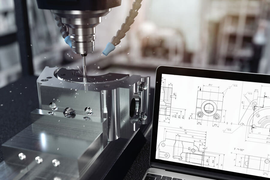
1. CAD Design
It all starts with a 3D model (STEP, IGES, or STL files) or 2D drawings. Your design should include dimensions, tolerances, and material specs—vague details can lead to costly revisions. Pro tip: Share both 3D and 2D files for clarity.
2. CAM Programming
Our engineers use CAM software (e.g., Mastercam, Fusion 360) to convert your CAD file into G-code—a language the machine understands. This step defines:
Tool paths (to avoid collisions and minimize waste).
Speeds (500–10,000 RPM, depending on material).
Feeds (how fast the tool moves through the material).
3. Machine Setup
Fixturing: The workpiece is clamped to a table (or vice) to prevent movement during cutting—critical for precision.
Tool calibration: Cutting tools (endmills, drills) are measured and loaded into the machine’s tool changer, with offsets programmed to ensure accuracy.
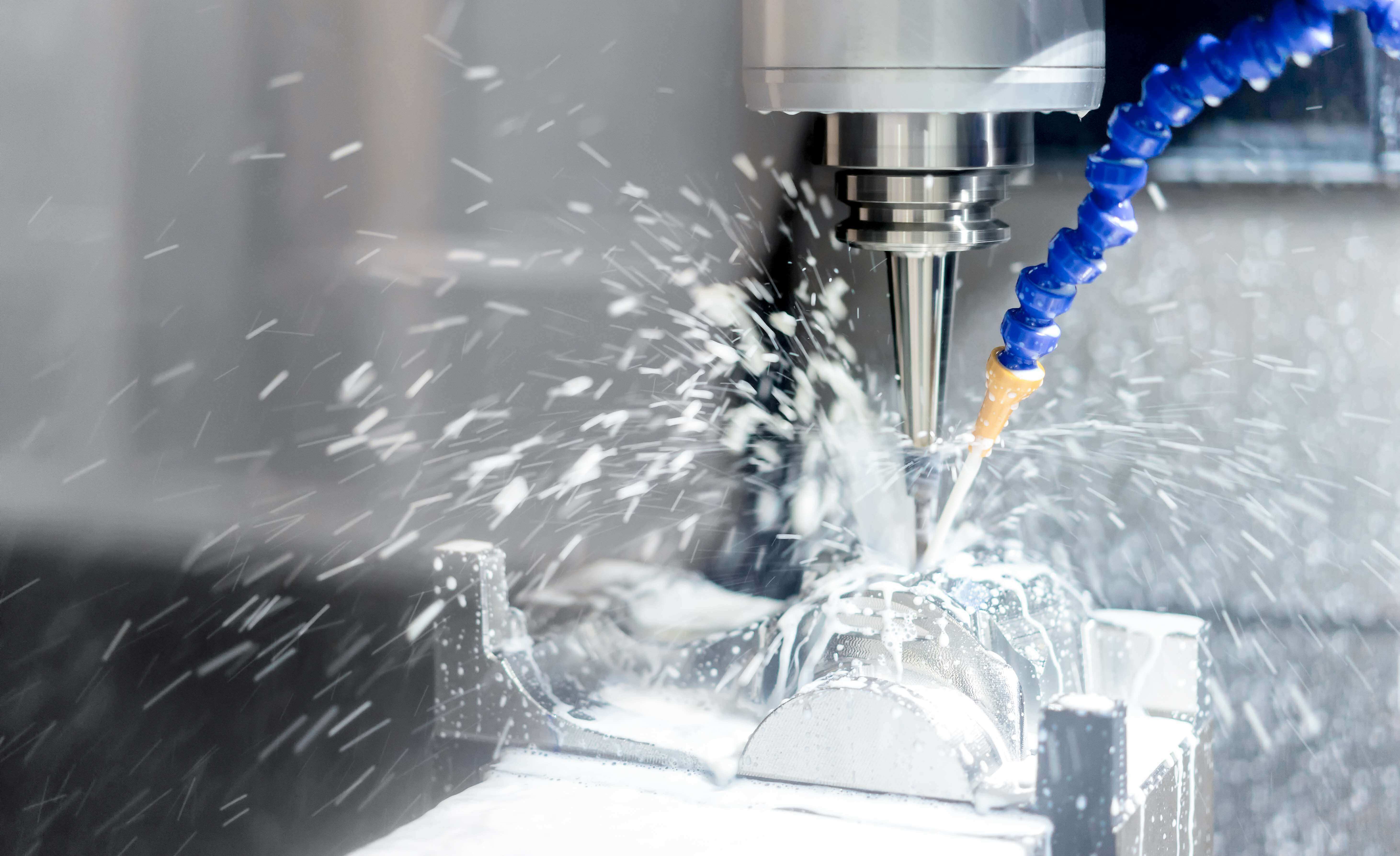
4. Machining Execution
The machine follows the G-code, removing material in layers. For complex parts, we run a “first article” (test part) to verify dimensions before full production—catching errors early saves time.
5. Post-Processing & Finishing
Deburring: Removes sharp edges (manual or automated, depending on part size).
Surface treatments: Anodizing (for aluminum), powder coating (for durability), or 电镀 (for corrosion resistance).
Heat treatment: Hardens metals (e.g., 4140 steel tempered to 30–35 HRC) for strength.
6. Quality Inspection
Basic checks: Calipers, micrometers, and height gauges for simple dimensions.
Advanced verification: CMM (Coordinate Measuring Machine) scans 3D geometry to confirm tolerances—we share full reports with critical parts.
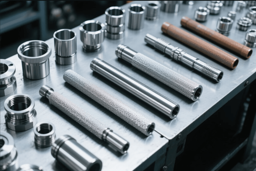
4. A Guide to Machinable Materials
Metals
| Material | Common Grades | Key Traits | Best For |
| Aluminum | 6061, 7075 | Lightweight, low cost, easy to machine | Automotive parts, enclosures |
| Stainless Steel | 303, 304, 316 | Corrosion-resistant, strong | Medical tools, marine components |
| Carbon Steel | 1018, 4140 | High strength, affordable | Structural brackets, shafts |
| Titanium | Grade 2, Grade 5 | High strength-to-weight, biocompatible | Aerospace parts, medical implants |
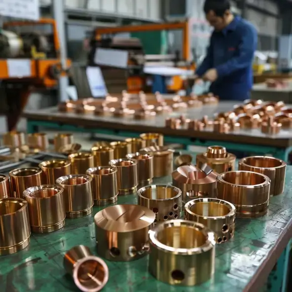
| Copper/Brass | C110, C360 | Excellent conductivity, machinability | Electrical connectors |
Plastics
ABS: Low cost, impact-resistant—good for prototypes.
PEEK: Heat-resistant (up to 260°C), chemical-resistant—ideal for medical and aerospace.
POM (Delrin): Low friction, high precision—used in gears and bearings.
5. Design for Manufacturability (DFM) Tips
Optimize your design to cut costs and avoid delays:
Internal Corner Radii: Sharp corners require small tools (prone to breakage). Use a radius ≥ tool diameter/2 (e.g., 6mm tool needs ≥3mm radius) to speed machining.
Wall Thickness: Keep walls ≥1mm (aluminum) or ≥0.8mm (plastics) to prevent warping during cutting.
Hole Depth-to-Diameter Ratio: Limit to 5:1 for standard drills (deeper holes need special tools, increasing cost).
Tolerances: Stick to standard tolerances (±0.05mm) unless critical—tight tolerances (±0.01mm) add 20–50% to cost.
Text & Engraving: Use bold fonts (≥12pt) and depth ≥0.2mm for readability; avoid fine details that blur during machining.
6. Key Factors Driving CNC Milling Costs
Machining Time: Complex geometries (e.g., 5-axis contours) take longer—simplify designs where possible.
Material Cost: Titanium costs 5x more than aluminum; high-purity grades add premiums.
Setup Costs: Custom fixtures or complex programming add one-time fees—minimize with standard designs.
Order Quantity: Batch production reduces per-unit cost (e.g., 100 parts cost 30% less per unit than 10 parts).
Finishing: Anodizing adds ~0.5–2/part; plating (e.g., nickel) adds more—only specify what’s necessary.
7. How to Choose a Reliable CNC Milling Partner
Check Equipment: Look for 5-axis machines (e.g., Haas, DMG Mori) and in-house CMMs—signs of precision capability.
Verify Certifications: ISO 9001 (quality), AS9100 (aerospace), or ISO 13485 (medical) ensure compliance.
Review Case Studies: Ask for examples of parts similar to yours—successful past projects reduce risk.
Evaluate Communication: A good partner offers DFM feedback upfront, with clear timelines and responsive support.
8. Conclusion & Call to Action
CNC milling turns complex designs into precise, reliable parts—whether you need 10 prototypes or 10,000 production units. By following this guide, you’ll streamline your project, avoid costly mistakes, and get parts that meet your specs.
Ready to start? Upload your CAD file today for a free quote—our engineers will review your design and share a detailed timeline. Let’s build something great together.