
")
CNC Machining Guide: How to Design CNC Machined Parts
We focus on the capabilities of modern CNC systems while ignoring related costs. For a guide on cost-effective CNC-machined parts, refer to this article.
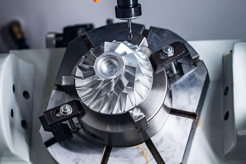
CNC machining is a subtractive technology. It uses various high-speed rotating tools (thousands of RPM) to remove material from a solid block to produce parts based on CAD models. Both metals and plastics can be CNC-machined.
CNC-machined parts feature high dimensional accuracy and strict tolerances. CNC is suitable for both mass production and one-off jobs. In fact, CNC machining is currently the most cost-effective method for producing metal prototypes, even when compared to 3D printing.
Main CNC Design Limitations
CNC offers great design flexibility but has certain limitations. These limitations are mainly related to the basic mechanics of cutting and tool geometry and access.
1. Tool Geometry
Most CNC tools (end mills and drills) are cylindrical with a limited cutting length.
When material is removed from the workpiece, the tool’s geometry is transferred to the machined part. For example, the inner radius of CNC parts always has a radius, regardless of the tool size.
2. Tool Access
Tools approach the workpiece directly from above to remove material. Features that cannot be accessed this way cannot be CNC-machined.
An exception to this is chamfering, which will be covered in a later section.
It is good design practice to align all part features (holes, cavities, vertical walls, etc.) with one of the six main directions. However, treat this as a recommendation rather than a strict limitation, especially since 5-axis CNC systems offer advanced work-holding capabilities.
Another issue arises when machining features with a large depth-to-width ratio. Special tools with long shanks are needed for deep cavities. This can reduce tool stiffness, increase vibration, and lower achievable accuracy.
Therefore, CNC experts recommend designing parts that can be machined with tools of the largest possible diameter and shortest possible length.
CNC Design Rules
Designing CNC-machined parts presents a challenge due to the absence of specific industry standards. However, CNC machine and tool manufacturers are continuously enhancing capabilities.
The following table summarizes the recommended and achievable values for common CNC-machined part features.
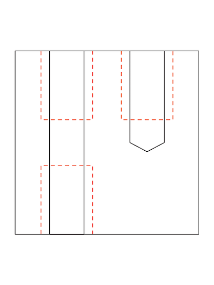
1. Cavities and Slots
The recommended cavity depth is four times the cavity width.
End mills have a limited cutting length, typically three to four times their diameter. When the depth-to-width ratio is small, tool deflection, chip evacuation, and vibration become significant. Limiting cavity depth to four times its width ensures good results.
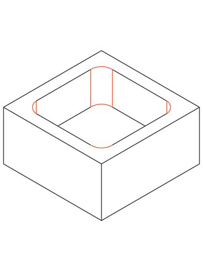
For greater depth, consider designing parts with variable cavity depth.
Deep cavity milling refers to cavities deeper than six times the tool diameter. Special tools allow a ratio of tool diameter to cavity depth up to 30:1. This means a 1-inch end mill can machine a maximum depth of 30 cm.
2. Inner Edges
The recommended corner radius is one-third of the cavity depth or larger.
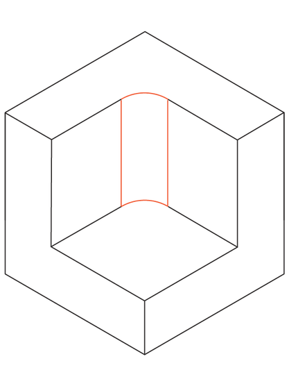
Using the recommended inner corner radius ensures a suitable tool diameter and aligns with cavity depth guidelines. Slightly increasing the corner radius above the recommendation (e.g., by 1 mm) allows the tool to cut along a circular path rather than a 90° angle. This approach is preferred as it results in a better surface finish. If sharp 90° inner corners are required, consider adding a T-shaped chamfer instead of reducing the corner radius.
The recommended bottom radius is 0.5 mm, 1 mm, or none. However, any radius is achievable. The bottom edge of an end mill is flat or slightly rounded. Other bottom radii can be machined with ball-end tools. Using recommended values is a good design practice as they are the machinist’s preferred option.
3. Thin Walls
The minimum wall thickness should be 0.8 mm for metal and 1.5 mm for plastic. However, thicknesses of 0.5 mm for metal and 1.0 mm for plastic are achievable.
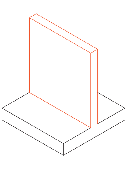
Reducing wall thickness decreases material stiffness. This increases vibration during machining and reduces achievable accuracy. Plastics are prone to warping due to residual stress and softening due to heat. Therefore, the larger minimum wall thickness recommendation is advisable for plastics.
4. Holes
The recommended diameter for holes is based on standard drill sizes. However, any diameter greater than 1 mm is achievable.
Holes can be machined with drills or end mills. Drills come in standardized sizes (metric and imperial). Reamers and boring tools are used for precision-tolerance holes. Standard diameters are preferred for holes smaller than ⌀20 mm.
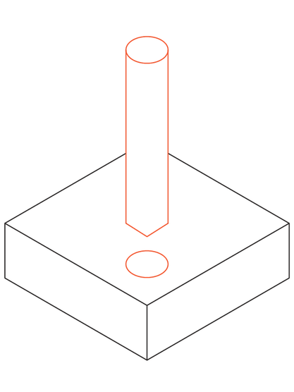
The maximum recommended depth for holes is four times the nominal diameter. Typical depths are ten times the nominal diameter, while achievable depths can be up to 40 times the nominal diameter.
For non-standard diameter holes, end mills must be used. In such cases, cavity depth limitations apply, and recommended maximum depth values should be used. Special drills with a minimum diameter of 3 mm can machine holes deeper than typical values. Blind holes drilled with drills have a tapered bottom (135° angle), while those machined with end mills have a flat bottom. There is no particular preference between through holes and blind holes in CNC machining.
5. Threads
The minimum thread size is M2, but M6 or larger is recommended.
Internal threads are cut with taps, and external threads with dies. Taps and dies can cut threads down to M2. CNC threading tools are commonly used and preferred by machinists as they reduce the risk of tap breakage. These tools can cut threads down to M6.
The minimum thread length is 1.5 times the nominal diameter, while the recommended length is three times the nominal diameter.
Most of the load on a thread is carried by a few of the first teeth, up to a maximum of 1.5 times the nominal diameter. Therefore, there is no need for threads exceeding three times the nominal diameter.
For threads in blind holes cut with taps (i.e., all threads smaller than M6), add an unthreaded length of 1.5 times the nominal diameter at the bottom of the hole.
When using CNC threading tools (i.e., for threads larger than M6), the hole can be threaded throughout its entire length.
6. Small Features
The recommended minimum hole diameter is 2.5 mm (0.1 inches), but diameters as small as 0.05 mm (0.005 inches) are achievable.
Most machine shops can accurately machine cavities and holes with diameters smaller than 2.5 mm (0.1 inches). However, anything below this limit is considered micro-machining. Special tools (micro drills) and expertise are required for such features due to the physical changes in the cutting process at this scale. Therefore, it is advisable to avoid these unless absolutely necessary.
7. Tolerances
The standard tolerance is ±0.125 mm (0.005 inches)
the typical tolerance is ±0.025 mm (0.001 inches)
and the achievable tolerance is ±0.0125 mm (0.0005 inches).